Building a Smart Central Heating System with a Raspberry Pi, and Python
My parents recently had a ‘smart thermostat’ installed. It got me to thinking: how hard could it really be to make one myself?
tldr; (original) public GitHub repository and README here
2023 Update: Check out the latest version on GitHub
Originally published 2020
Even as a young child I can remember craving technology: miniature portable technology in particular. From the mini TVs and games systems of the early 90s, through the Palm Pilots and Nokia Communicators of the late 90s, to the handheld heaven that emerged at the turn of the millennium, I’ve consistently coveted other people’s gadgets! I used to think miniature electronic devices and things like ‘home automation’ were pursuits of the wealthy: the Bruce Waynes and Tony Starks of this world. That was until yesterday when I received this:
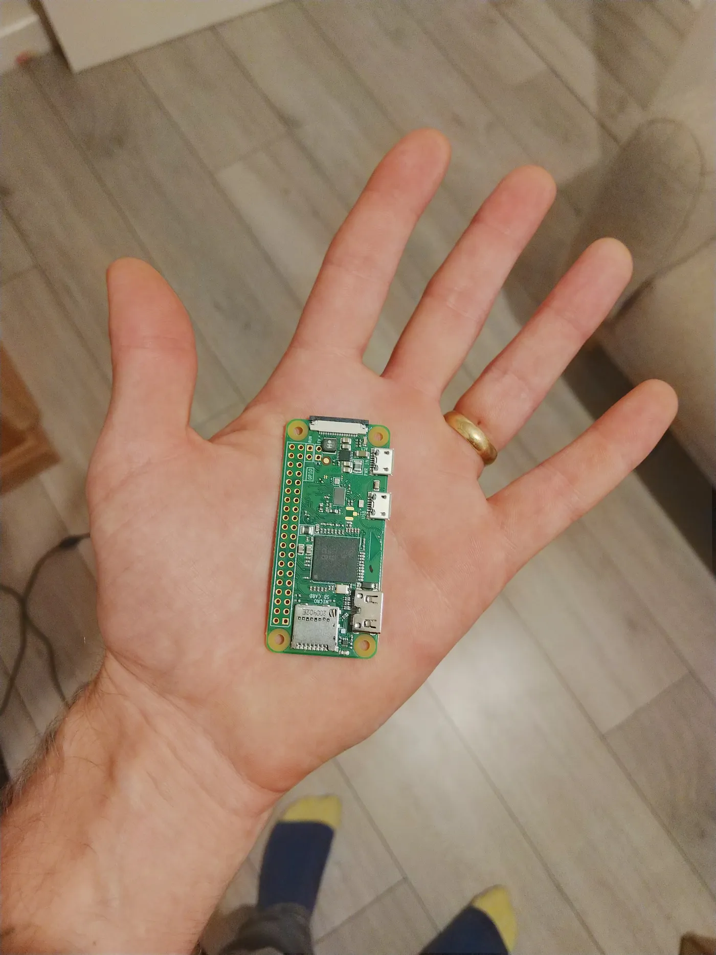 Raspbery Pi Zero W
Tiny, isn’t it!? That’s a single board computer: as in, a whole computer on a single (tiny) board, a.k.a. the Raspberry Pi Zero W… And it only cost 7quid*! Now, of course, I’m being melodramatic for the purposes of the introduction ( skip to the end if you’re itching to get to the code ); I, of course, already knew of the existence of SBCs and, in fact, have owned a Pi 3B for a number of years now and used it for various things: games console emulator, media center, file server, web server, kali linux experiments, etc etc.. and let’s be honest, they do all of these things adequately, but not especially brilliantly — a Raspberry Pi 3 media center certainly leaves a lot to be desired!
However, I didn’t start to realise the real potential of such a device until recently. It turns out the real super power of a Raspberry Pi is in its GPIO pins (General Purpose Input/Output). I’d actually seen a whole load of YouTube videos, including those of a long-time personal favourite channel of mine, Christopher Barnatt’s Explaining Computers, which describe in detail various projects and experiments which make use of these pins, but, as is often the case, by all accounts, with YouTube-addicted-hacker-maker-wannabes like myself, I had no worthy project of my own in mind to stimulate me, and therefore had not yet bothered experimenting myself.
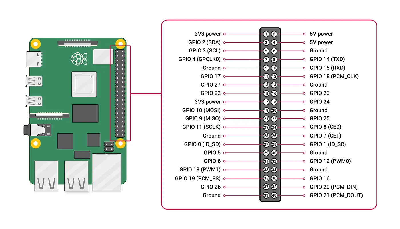 GPIO Pins on a Raspberry Pi SBC (from here)
Other things that stopped me:
- worry that I would blow up my one and only Pi
- cost of buying peripherals such as jumper cables/modules/breadboard etc.
- general laziness
In answer to the first two, I can now say that 1: with minimal research you come to realise how simple the layout of the pins is and that the majority of the pins are more-or-less exactly the same — just waiting for you to define them — and 2: the cost is extremely low, especially with adequate prior planning: more affordable third-party parts might take longer to arrive/source. Additionally, in spite of all that, for my initial tests I was able to sacrifice a few cables from elsewhere and mash them haphazardly onto the GPIO pins without issue (and in so doing, offer further reassurance to worry number 1!). In addition, as one of the aforementioned hacker-maker-wannabes, I have already amassed such bare essentials as solding irons and tiny screwdrivers, as I’m sure is the case for many people reading, and I never needed a breadboard after all.
Number 3 is just life unfortunately, and we all deal with our laziness in our own ways, but it definitely stems back to the point about having a worthy project and coming up with a plan.
*quid: British money
A worthy project…
I moved into a new house a year ago, and this winter the central heating system has really demonstrated its limitations. We have a separate downstairs/ upstairs loop, each with its own programmer. The programmer is of a type that you set the temperature at 4 times during the day, on either a week-day or a week-end. So, you could, for example, set it to warm up to 20°C at 6am, then down to 5° at 8am (if nobody’s at home) and up to 20° again at 6pm, and then down to 5° again at bedtime, and different on Saturday and Sunday if need be. It’s a combined system; most I’ve had in the past have had separate thermostat and timer units, and I have to say, I think combining the two, while saving wall space, actually restricts the functionality; especially since, in the case of the model on our wall, there is no advance (+1hr) button. The only thing you can do, if you want some non-standard heat-time, is laboriously notch up the temperature on the digital display until it goes above the threshold, and then it will stay like that until the next change unless you remember to (laboriously) notch it back down, which is seldom desirable. This annoyance, along with my parents’ having installed a ‘smart thermostat’ with an app, and my own growing desire to be able to warm up the house from afar, got me to thinking: how hard could it really be to make one myself?
Setting up a mains relay with Raspberry Pi GPIO pins.
Pulling the programmer off the wall, I saw that behind it was a simple single-channel relay. We’re lucky in the UK not to need air conditioning and/or fans; if it’s ever unbearably hot, it’s usually only for 2 or 3 days at a time, so we don’t bother… lucky because it makes hacking my house a whole lot more straightforward (…not so lucky about the weather!).
 Simple relay, bottom left, in normally open (N/O) position.
This was what I was expecting to be honest: temperature goes below threshold, click (unmistakeable sound of a relay), boiler fires up; temperature goes back above, click, boiler chills out; so I checked online for the cheapest possible relay that would interface with my Pi. I was extremely excited for, but still mildly apprehensive towards my first GPIO project.
The model I settled on was the Adafruit Power Relay Featherwing. This 5A 250V relay could apparently handle UK mains voltage and be triggered effectively by the Pi’s 3volt pin. (Other cheaper examples came with warnings from reviewers about non-ideal results when trying to work with the Raspberry Pi’s 5v pin.) When it arrived, I saw that it had almost as many holes for GPIO pins as the Pi! This confused me slightly at first, but again, at the end of the day, it was down to me to choose my own location for the signal pin (one of the three needed; the others being 3-volt power and GND [ground]). The 3V and GND were easy enough to locate on the Pi, and the signal, as it turned out, could also be connected to any one of the standard GPIO pins on the Pi. I connected the pins to the Pi like so:
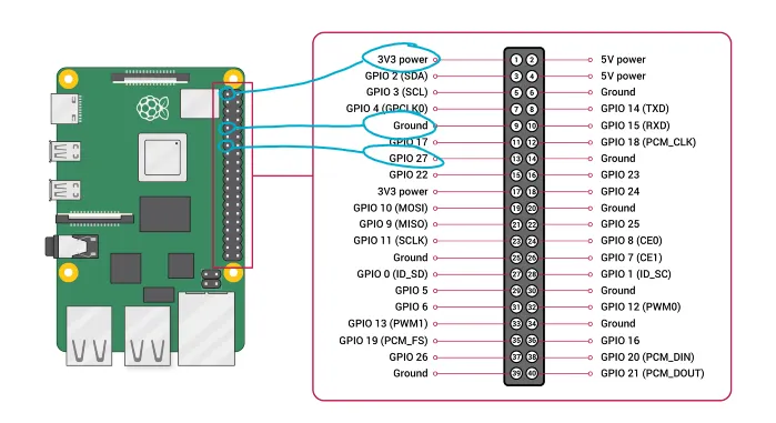 3V connected to pin 1, GND connected to pin 9 and Signal connected to pin 13 (GPIO 27)
When the relay arrived, I could move on to the next stage of the project: writing some code…. finally! I used a test script based on one I’d seen on Explaining Computers.
Testing the relay for the first time.
import RPi.GPIO as GPIO
import time

GPIO.setmode(GPIO.BOARD)

GPIO.setup(13, GPIO.OUT)

try:
    while True:
        GPIO.output(13, True)
        time.sleep(1)
        GPIO.output(13, False)
        time.sleep(1)

finally:
    GPIO.cleanup()
In the code example above, after importing the RPi.GPIO libary, I set the board numbering mode to sequential, and then set my chosen signal pin, pin 13, as an output pin. Then I initiate a while loop that clicks the relay on and off with a second’s delay. The try/finally block removes the settings before exiting the program. It worked first time (thanks Chris!) and it was incredibly satisfying to hear the click and watch my script interacting with a physical object!
There were a whole load of pins spare, which is good because I also needed to attach a temperature module. Again after some research I settled on the cheapest option without any negative reviews, the BMP280 (originally manufactured by Bosch):

And after a quick search found this helpful diagram and tutorial for how to wire it up to the Pi:
In this case the pins you use are important as pins 3 and 5 (GPIO 2(SDA) & 3(SCL)) are intended for I²C usage.
Using the configuration above, I would probably have to move the relay’s 3V cable to the Pi’s 3V pin at position 17 but otherwise, the temperature sensor shouldn’t interfere with the relay. I wired it up without issue:
 The temperature module hanging from salvaged cables (later replaced)
Obviously I first wrote some simple scripts to test the relay and sensor module and while the former was incredibly easy to get going, the latter was a little tricky due to the data transfer aspect relying on the Pi’s I2C pins. There are various permissions issues when using these pins, especially when not running the Raspian OS (I’m running Ubuntu 20.04), but nothing that couldn’t be solved with a few searches of Google/StackOverflow. The main issue came down to my old friend, PermissionError, when trying to run the script not as root (not ideal when you want it to run autonomously on a webserver). In the end I found a fantastic package called pigpiowhich when the pigpiod daemon is running on your system, bypasses these permissions. It can be used instead of RPi.GPIO and it is considerably easier to configure. On Ubuntu (and Raspian) you can install it with the following command:
sudo apt install pigpiod
and then install the Python module with:
pip3 install pigpio
There are various other dependencies; I also needed to install smbus2 and pimoroni-bme280 with:
pip3 install smbus2 pimoroni-bme280
Troubleshooting
Another helpful thing to install is i2c-tools which helped me debug an issue that came down to bad soldering.
sudo apt install i2c-tools
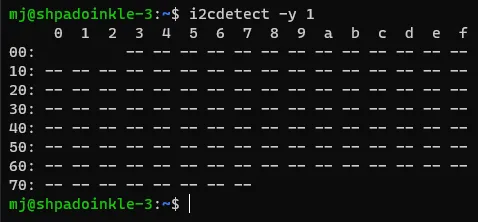
This allows you to use i2cdetect to see the I2C addresses that are currently in use. If nothing is connected, the output will look like this:
If you’ve installed all the dependencies and you’re still not picking anything up, it’s time to check your wiring, and in my case, I wasn’t really too happy with the soldering job I’d done, so I started there. When soldering the tiny GPIO pins to the Pi Zero W, I hadn’t made sure that every blob of solder had melted right into the hole, as it’s supposed to do, so I went back over it and sorted this out, and was extremely relieved when the module immediately got detected by i2cdetect:
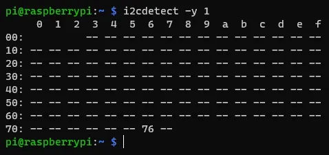 As you can see, something has been detected at address 76 (exciting!).
(This was the closest I came to giving worry number 1 from earlier any validation. I was mainly concerned that I would solder all of the tiny pins together by accident and short the board. However, I escaped with my Pi in tact, albiet with some laughably inconsistant blobs of solder across the bottom!)
The code
Hardware debugging completed, it was time to write some proper code (finally!).
I decided to construct a class for the heating system that would take care of all the different things that needed to be done. In this way, it can be easily imported into another project, such as a Flask application.
import json
import time
from datetime import datetime
from threading import Thread
import pigpio
import requests
from requests.exceptions import ConnectionError


class Heating:
    def __init__(self):
        self.pi = pigpio.pi()
        self.advance = False
        self.advance_start_time = None
        self.on = False
        self.tstat = False
        self.temperature = self.check_temperature()
        self.humidity = self.check_humidity()
        self.pressure = self.check_pressure()
        self.desired_temperature = 20
        self.timer_program = {
            'on_1': '07:30',
            'off_1': '09:30',
            'on_2': '17:30',
            'off_2': '22:00',
        }

    def thermostatic_control(self):
        self.tstat = True
        while self.tstat:
            time_check = datetime.strptime(datetime.utcnow().time().strftime('%H:%M'), '%H:%M').time()
            on_1 = datetime.strptime(self.timer_program['on_1'], '%H:%M').time()
            off_1 = datetime.strptime(self.timer_program['off_1'], '%H:%M').time()
            on_2 = datetime.strptime(self.timer_program['on_2'], '%H:%M').time()
            off_2 = datetime.strptime(self.timer_program['off_2'], '%H:%M').time()
            if (on_1 < time_check < off_1) or (on_2 < time_check < off_2):
                if self.check_temperature() < int(self.desired_temperature) and not self.check_state():
                    self.switch_on_relay()
                elif self.check_temperature() > int(self.desired_temperature) + 0.5 and self.check_state():
                    self.switch_off_relay()
                time.sleep(5)
            else:
                if self.check_state():
                    self.switch_off_relay()
                time.sleep(900)
        return

    def thermostat_thread(self):
        self.on = True
        t1 = Thread(target=self.thermostatic_control)
        t1.daemon = True
        t1.start()

    def stop_thread(self):
        self.on = False
        self.tstat = False
        self.switch_off_relay()

    def sensor_api(self):
        try:
            req = requests.get('http://192.168.1.88/')
            data = json.loads(req.text)
            return data
        except ConnectionError:
            return {
                'temperature': self.temperature,
                'humidity': self.humidity,
                'pressure': self.pressure,
            }

    def check_temperature(self):
        self.temperature = self.sensor_api()['temperature']
        return self.temperature

    def check_pressure(self):
        self.pressure = self.sensor_api()['pressure']
        return self.pressure

    def check_humidity(self):
        self.humidity = self.sensor_api()['humidity']
        return self.humidity

    def switch_on_relay(self):
        self.pi.write(27, 1)

    def switch_off_relay(self):
        self.pi.write(27, 0)

    def check_state(self):
        return self.pi.read(27)

    def start_time(self):
        if not self.advance_start_time:
            self.advance_start_time = datetime.now().strftime('%b %d, %Y %H:%M:%S')
        return self.advance_start_time


if __name__ == '__main__':
    hs = Heating()
    while True:
        print(f'''________________________________________________________________
{datetime.utcnow().time()}
Temp: {hs.check_temperature()}
Pressure: {hs.check_pressure()}
Humidity: {hs.check_humidity()}
________________________________________________________________
        ''')
        time.sleep(2)
So, it’s quite long! I included various checks that would be needed by the Flask application/front-end; the start_time() method for example, is to create a variable which is passed to the html template to allow for a consistent JavaScript countdown timer, regardless of whether the page is refreshed, or a different device is used.
A Thermostat API
As you might have noticed, the script above doesn’t actually contain the functions for checking the temperature module itself, and that was because I found it more convenient to leave my Pi 3B that I had been testing on set up with the relay, and to have a more portable Pi Zero W which could then serve up the data from the sensor module via an API. The code for that very simple Flask API with the BME280 methods is as follows:
#!/usr/bin/env/python3
import time

import pigpio
from smbus2 import SMBus
from bme280 import BME280

from flask import Flask, jsonify, make_response
app = Flask(__name__)

pi = pigpio.pi()
bus = SMBus(1)
bme = BME280(i2c_dev=bus)

# throwaway readings:
for i in range(3):
    bme.get_temperature()
    bme.get_humidity()
    bme.get_pressure()


@app.route('/')
def sensor_api():
    response = make_response(jsonify({'temperature': bme.get_temperature(),
                                      'humidity': bme.get_humidity(),
                                      'pressure': bme.get_pressure()}))
    response.status_code = 200
    return response
The single endpoint returns a JSON response with the sensor data at that moment in time.
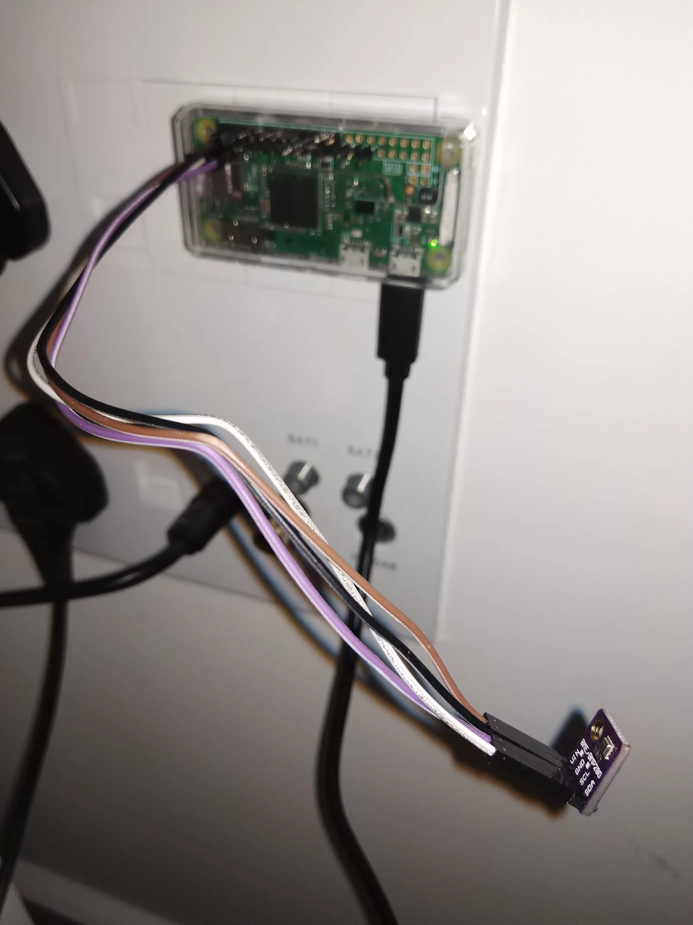
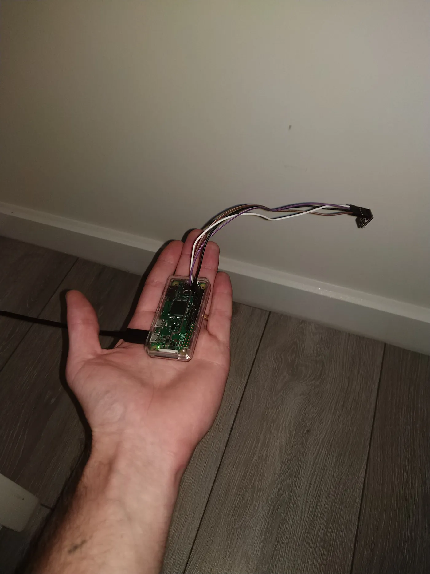 The new satellite thermostat API system. Source of soldering issues mentioned above.
Reverse engineering my central heating system.
The nice thing about electronics is that the majority of components are nicely labeled and documented. When it comes to electrics, this is rarely the case! When I took the cover off the junction box in my airing cupboard, there were a number of different wires serving the two actuator valves that deal with the two heating loops: an indistinguishable mess of wires coming in through a hole in the wall, and 4 going out to each actuator, for a total of 8.
I searched around and found the official documentation for the actuator valves and was able to work out what the 4 different wires were and which one was the crucial ‘live’ that was being broken by the relay in the programmer-unit on the wall. (This took a lot longer to work out than I’m making it sound — not helped by the fact that all of the wires coming in from the rest of the house seemed to be brown! I watched a huge number of YouTube videos on “how to wire a central heating system UK” in an effort to understand it.)
Then, it was just a case of closing the relays on the wall and breaking the circuit inside the airing cupboard with my relay, powering both the actuators at the same time. I also decided to add a plug socket to the cupboard while I was there to give the Pi some power, enabling me to give my router a new out-of-the-way home (my wife is extremely pleased as she hates wires) — the signal has barely suffered from it’s being inside a cupboard which is surprising!
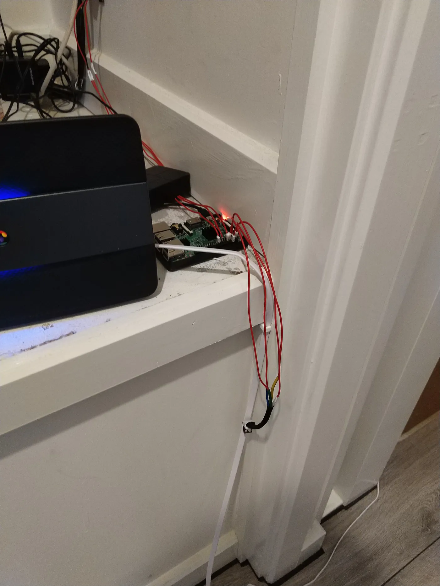
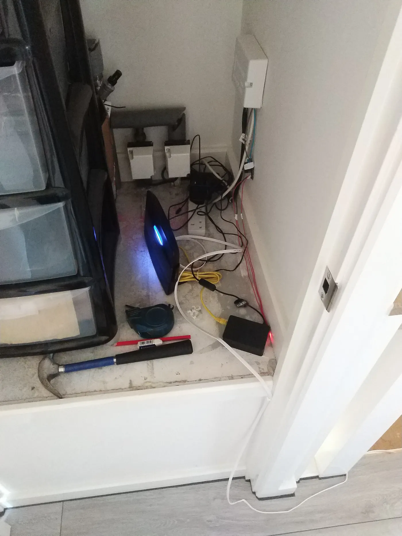 In the process of re-routing the router. Relay can be seen hanging from the wall, and Pi in black box.
Essentially, there was one circuit leading away from the actuators towards the pump that was to be left alone, and two circuits going to the programmers on the walls, upstairs and downstairs. As I said, I closed one relay and used that circuit for the plug socket extender you see there. I’ll make a more permanent solution at some point. For now this is fine.
The Front End (GUI)

I actually built out the front-end routes and templates in the early stages since it went hand in hand with testing the system. (I also had to wait several days for the temperature module, so had a half-baked version that was purely timer based that I wanted to start using.) Again, the Flask app is pretty simple. I just needed routes/views for ‘/’ ‘/on’ ‘/off’ ‘/advance’ and ‘/settings’. I also played with adding a music feature, but I won’t go into it here. I have left in my rudimentary authentication system, which relies on a simple codeword stored in plain text. I could encode this fairly easily, but again, I’ll leave that for now. It’s another long piece of code, but there are some nice images of the UI and the ‘finished’ product at the end. (I won’t bore you with the html and custom css, but will make a public repository at some point on my Github)
#!/usr/bin/env python3
import time
from threading import Thread
from flask import Flask, redirect, url_for, render_template, request, session, jsonify, make_response
from .heating import Heating
app = Flask(__name__)
hs = Heating()
# Throwaway temp checks:
hs.check_temperature()
time.sleep(1)
hs.check_temperature()
@app.route('/heating')
def home():
if 'verified' in session:
start_time = hs.start_time() if hs.advance else None
return render_template('heating.html', on=hs.on, relay_on=hs.check_state(),
current_temp=int(hs.check_temperature()), desired_temp=int(hs.desired_temperature),
advance=hs.advance, time=start_time,
)
return redirect(url_for('login'))
@app.route('/', methods=['GET', 'POST'])
def login():
if request.method == 'GET':
if 'verified' in session:
return redirect(url_for('menu'))
return render_template('login.html')
else:
name = request.form.get('name')
if name == 'PASSWORD':
session['verified'] = True
return redirect(url_for('menu'))
else:
return render_template('login.html', message='You are not allowed to enter.')
@app.route('/menu')
def menu():
if 'verified' in session:
return render_template('menu.html')
return redirect(url_for('login'))
@app.route('/on')
def on():
if 'verified' in session:
hs.thermostat_thread()
return redirect(url_for('home'))
return redirect(url_for('login'))
@app.route('/off')
def off():
if 'verified' in session:
hs.stop_thread()
hs.advance = False
hs.advance_start_time = None
return redirect(url_for('home'))
return redirect(url_for('login'))
def advance_thread():
interrupt = False
if hs.tstat:
hs.tstat = False
interrupt = True
hs.switch_on_relay()
time.sleep(900)
hs.switch_off_relay()
hs.advance = False
hs.advance_start_time = None
hs.on = False
if interrupt:
hs.thermostat_thread()
@app.route('/advance')
def advance():
if 'verified' in session:
hs.on = True
hs.advance = True
t1 = Thread(target=advance_thread)
t1.daemon = True
t1.start()
return redirect(url_for('home'))
return redirect(url_for('login'))
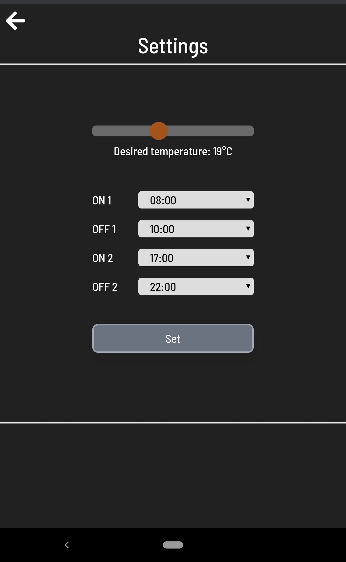
@app.route('/settings', methods=['GET', 'POST'])
def settings():
if request.method == 'GET':
if 'verified' in session:
return render_template('settings.html', des_temp=hs.desired_temperature, timer_prog=hs.timer_program)
return render_template('login.html')
else:
interrupt = False
if hs.tstat:
hs.tstat = False
interrupt = True
des_temp = request.form.get('myRange')
on_1 = request.form.get('on_1')
off_1 = request.form.get('off_1')
on_2 = request.form.get('on_2')
off_2 = request.form.get('off_2')
new_timer_prog = {
'on_1': on_1,
'off_1': off_1,
'on_2': on_2,
'off_2': off_2
}
hs.desired_temperature = des_temp
hs.timer_program = new_timer_prog
if interrupt:
hs.thermostat_thread()
return redirect(url_for('home'))
@app.route('/temp', methods=['GET'])
def fetch_temp() -> int:
response = make_response(jsonify({"temp": int(hs.check_temperature()),
"on": hs.check_state()}), 200)
return response
@app.route('/radio')
def radio():
return render_template('radio.html')
@app.errorhandler(404)
def page_not_found(e):
return redirect(url_for('home'))
if __name__ == '__main__':
app.secret_key = 'SECRET KEY'
app.run(debug=True, host='0.0.0.0', port=5000)
I wonder if in the responses anyone can find the obvious security flaw that I’ve left in?!
Again there are various extra things, like the fetch_temp() view/api, which was included purely for styling purposes. The view responds to an asynchronous request from a javascript function to allow updating the temperature display in real time and changing its colour to red when the relay is switched on:
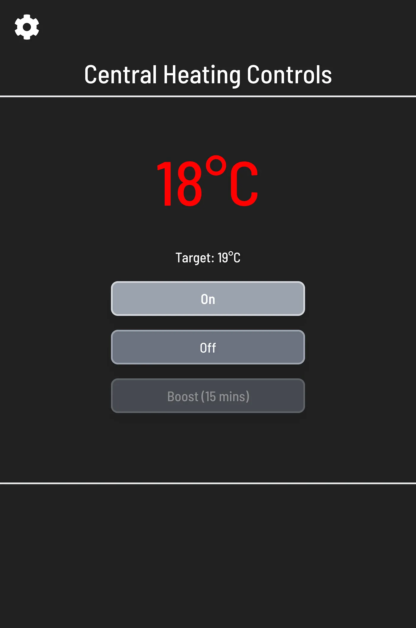 The temperature module (a slightly different version to the one pictured above, without the two extra pins.)
 Salvaged cables replaced with colour coded jumper cables.
 Discretely place behind the TV, although this later turned out to be too cool an area to be effective.
So, that’s pretty much it. There’s plenty to keep tinkering with and smartening up, and I look forward to it! The whole thing’s cost me about £30 (quid) give or take so far, but I’m sure I’ll sink a bit more into it with said tinkering! (I also already had the Pi 3B.) Thanks for reading, and I hope I’ve shown you, as I’ve shown myself, that all this stuff really isn’t that hard.